This article outlines the main operations to be performed with PT series welders for proper butt welding.
As a reminder, welding of pressurized pipelines can only be performed by properly trained personnel at a training institution with the appropriate license!
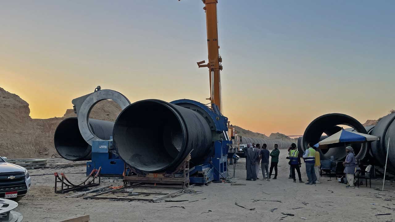
1. Positioning and preparation of the welding machine
Welding machine components should be placed on a flat, even surface.
It is recommended to use wood panels as a base if possible, so as to reduce contact with the ground as much as possible and consequently the accumulation of dirt on the pipe heads.
The recommended arrangement of the elements is shown in the picture.
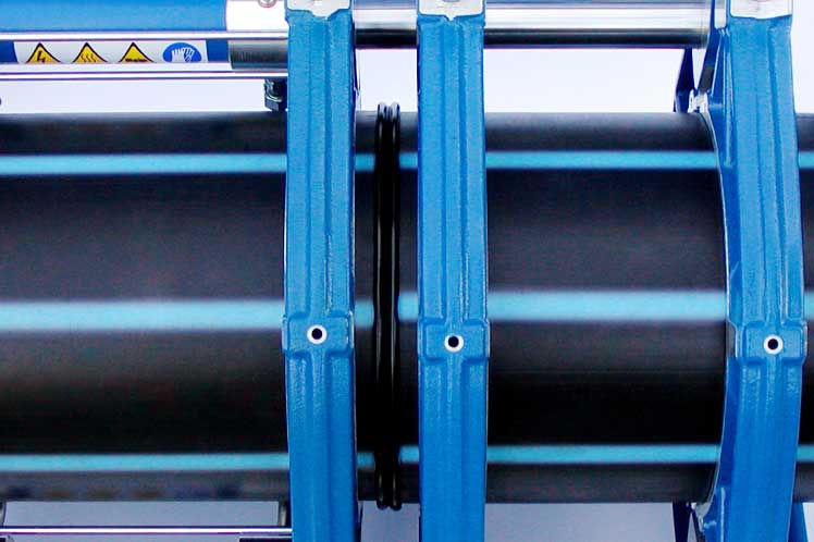
When used on construction sites, the use of special roller conveyors is suggested to facilitate the sliding of the tubes to be welded and to avoid subjecting the machine to excessive strain.
Connect the hydraulic power unit to the base body with the quick couplers provided.
Connect the power pack, cutter and thermoplate to the power point after making sure that the supply voltage matches their rated voltage within 10%.
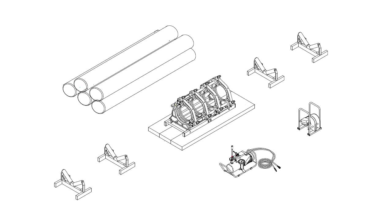
Watch your hands! The heating element starts to heat up!
Adjust the temperature of the heating element according to the diameter thickness and material of the pipe to be welded (see attached tables in the manual).
Select the reductions corresponding to the diameter of the pipe to be welded (the diameter value is stamped on the reductions themselves), mount the eight half-rings by inserting them into the housing slots of the clamps, securing them with the appropriate screws. Each set of reductions includes two "narrow" half-rings to facilitate gripping short spigot fittings.
2. Positioning and preparation of the welding machine
Prepare the movable carriage in the fully open position.
Remove the upper clamps by loosening the tightening nuts.
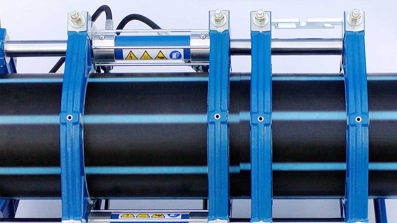
Position the two tubes/fittings to be welded taking care to leave enough space for the introduction of the cutter, remount the upper clamps and tighten the nuts.
Check the alignment of the pipes/fittings by bringing the surfaces to be welded closer together; any misalignment can be corrected by acting on the center clamp nuts or by rotating the pipes. The maximum misalignment cannot exceed 10% of the thickness of the tube/fitting up to a maximum of 2 mm.
Clean the ends of the pipes/fittings by completely removing all traces of dust and dirt, clean with a suitable detergent if necessary.
Introduce the cutter between the surfaces to be welded by inserting it into the appropriate slots of the base body, insert the safety plug, and start the motor.
Slowly bring the ends of the pipes/fittings to be welded closer to the cutter blades, which will begin to remove material; if this does not happen, increase slightly the pressure(an excessive increase may result in motor burn-out). Milling can be considered finished when the chips come out continuously and evenly on both sides and the width of the chips is equal to the thickness of the pipe/fitting. Turn off the milling cutter and store it in the case provided.
Bring the surfaces to be welded into contact and check that any gap is less than the limits prescribed by the standard used.
3. Detection of inertia pressure
Before starting the welding cycle, the value of the inertia pressure should be noted; this value should be added to the welding pressures in the tables in the manual. The value of the drag pressure depends on the welding operating conditions (e.g., length and weight of the pipe to be dragged, general machine conditions, ambient working temperature, etc.).
How to detect the drag pressure?
- Fully open the carriages of the machine by operating the lever as indicated in the manual.
- Turn the pressure regulator-knob counterclockwise to the end stop.
- Turn the pressure-by-pass lever clockwise to the end stop.
- Move the lever to the wagon closing position (the wagons do not close being zero pressure).
- Slowly turn the pressure regulator-knob clockwise until the floats slowly begin to move.
- While the wagons are moving, read the relevant pressure (=drag pressure) on the pressure gauge,
4. The welding cycle
The welding cycle is divided into 6 distinct PHASES:
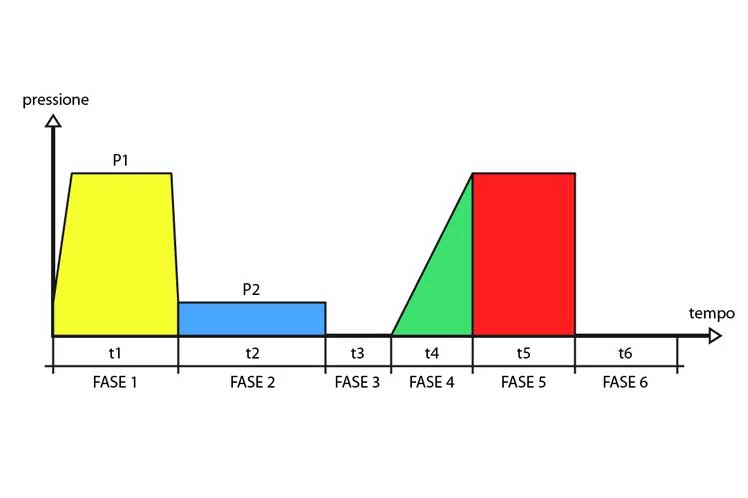
PHASE 1 Approaching and preheating (under pressure)
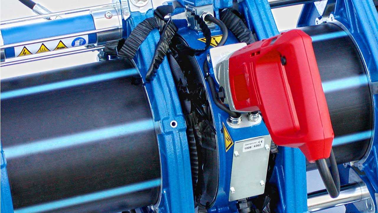
Insert the thermocouple between the elements to be welded, turn the thermocouple detachment towards the inside of the machine, jamming the support fork into it. increase the thrust pressure by acting on the lever and with the lever of the distributor in the coupling position. The value of the pressure being exerted can be read on the pressure gauge in bar .
This phase ends after a time t 1 as soon as a ring of molten material appears on the ends to be welded, the width of which is indicated in the welding tables.
PHASE2 Heating
When the 'molten ring appears, the pressure is reduced by turning the lever counterclockwise and kept constant for a time t 2
PHASE3 Removal of the thermoelement
After the time t 2 has elapsed, the pressure must be brought to zero (by turning the lever E counterclockwise) and the two faces of the tubes to be welded must be quickly removed (by bringing the distributor lever to the open position) from the thermoplate to allow the removal of the thermoelement. It is important to verify that the thermoplate detachment has positioned itself toward the 'outside of the machine after removing the thermoelement.
Reapproach the two surfaces to be welded by closing the carriages and acting on the lever-by-pass to obtain a pressure slightly higher than the drag pressure ( so as not to have an abrupt release of material at the moment of contact between the two surfaces).
STEP 4 Reaching the welding pressure
Having made contact between the two surfaces to be welded, the pressure must be gradually and continuously raised to the pressure value P5 of STEP 5 in a time t 4 by turning the lever-by-pass clockwise and with the distributor lever in the position-closing carts
STEP5 Welding under pressure
The pressure value reached in the previous step must be maintained for a time t 5 . During this step, the distributor lever should be moved to the neutral position since the pressure value is maintained even when the engine is off.
Having performed the welding before loosening the upper clamps, the pressure should be brought to zero.
STEP6 Rest or cooling time (outside the machine).
When the pressure welding phase is finished and the workpiece is removed from the machine, it is good practice to wait an additional period of time t 6 (minutes) before stressing the weld (pressurizing , heavy transport or other).
This last phase is not required by all standards.
CHECK
Successful welding should always be visually checked by the operator!